
UHF RFID Reader Antenna Polarization: Linear vs Circular for Handheld Devices


UHF RFID reader antenna polarization determines how the reader’s electromagnetic field interacts with RFID tag antennas. Linear polarization is often effective when tag orientation is controlled, while circular polarization provides more consistent coupling when tags face different directions. For handheld devices, the appropriate choice depends on tag placement, reading distance, asset materials, and the operator’s scanning movement.
A linearly polarized antenna can offer a useful range advantage when its orientation matches the tag. However, rotating the tag or reader may significantly reduce the available signal.
Circular polarization reduces this sensitivity, making it practical for warehouse inventory, equipment inspections, and mobile asset identification. Neither option guarantees reliable detection without suitable tags and properly configured reader hardware.
What Is UHF RFID Antenna Polarization?
Polarization describes the orientation and behavior of the electric field in an electromagnetic wave.
In a passive UHF RFID system, the reader transmits radio-frequency energy toward a tag. The tag captures part of that energy and communicates by modulating its reflected signal.
The polarization of the reader antenna affects how efficiently that energy couples into the tag antenna.
Most conventional passive UHF RFID tags use antenna structures with predominantly linear polarization.
The RAIN Alliance explains that reader antennas can operate with horizontal, vertical, or circular polarization, depending on the intended application.
Linear Polarization
A linearly polarized antenna radiates an electric field with a fixed polarization direction.
Two common orientations are horizontal and vertical.
When a linearly polarized reader antenna aligns with a linearly polarized tag antenna, coupling can be efficient.
However, rotating one antenna relative to the other reduces the effective field component received by the tag.
At a near-perpendicular orientation, ideal linear antennas experience severe polarization mismatch.
In practice, reflections and antenna design may still allow occasional reads.
This makes linear polarization useful when the positions and orientations of tagged assets remain predictable.
Circular Polarization
A circularly polarized antenna produces an electric field whose direction rotates as the wave propagates.
This allows it to interact with a conventional linear tag antenna across a wider range of tag orientations.
Circular polarization is particularly useful when employees cannot control how equipment, cartons, or containers face the reader.
However, the antenna still has a directional radiation pattern.
A circularly polarized reader cannot detect every tag behind obstacles or outside its effective coverage area.
Its main advantage is reduced sensitivity to polarization alignment, not unlimited reading coverage.

Linear vs Circular Polarization: Performance Differences
The best antenna design depends on whether the application prioritizes efficient coupling at a known orientation or consistent detection across varied orientations.
| Factor | Linear Polarization | Circular Polarization |
|---|---|---|
| Electric field | Fixed orientation | Rotating orientation |
| Tag alignment | Important for maximum coupling | Less sensitive to tag rotation |
| Potential range | Advantage when correctly aligned | May have lower range under otherwise comparable conditions |
| Random tag orientation | Greater risk of missed reads | Generally more consistent |
| Typical application | Controlled tag placement | Mobile inventory and mixed-orientation assets |
| Main limitation | Polarization mismatch | Polarization-related coupling loss with linear tags |
| Field testing | Verify alignment and range | Verify coverage and unintended reads |
These differences assume comparable antenna designs and operating conditions.
A real reader’s performance also depends on antenna gain, radiation pattern, chip sensitivity, transmit power, and the surrounding environment.
Understanding Polarization Mismatch Loss
When an ideal circularly polarized wave reaches an ideal linearly polarized receiving antenna, only half the incident power can couple through polarization alignment.
This corresponds to approximately 3 dB of polarization mismatch loss.
A properly aligned linear-to-linear antenna pair does not experience this particular loss.
However, a linearly polarized pair can experience much greater loss when the tag rotates away from the preferred orientation.
Therefore, the 3 dB figure should not be interpreted as a fixed difference in total reader performance.
Actual read range also depends on other factors in the RFID link budget.
Does Linear Polarization Always Read Farther?
No. Linear polarization can provide better coupling when the tag orientation is controlled, but it does not automatically produce greater range in every installation.
A poorly matched or incorrectly aimed linear antenna may perform worse than a circularly polarized alternative.
Differences in antenna gain, beamwidth, transmit power, and tag sensitivity can also outweigh polarization effects.
Siemens’ technical guidance on selecting UHF RFID antennas recommends circular polarization when tag orientation is unknown or changes during operation.
For handheld systems, the working conditions should determine whether maximum aligned range or orientation tolerance matters more.
How Polarization Affects Handheld RFID Scanning
Handheld RFID readers create a different operating environment from fixed readers.
The operator changes the antenna position continuously while walking, aiming, and inspecting tagged assets.
The tag may also be mounted horizontally, vertically, or at an angle.
These movements alter the relationship between the reader and tag antennas.
Warehouse Inventory with Mixed Tag Orientations
Warehouse employees often scan cartons and containers arranged in different positions.
Some tags face forward, while others face sideways or upward.
With linear polarization, these different orientations may produce inconsistent read results.
Circular polarization can reduce this problem by allowing stronger coupling across varying tag rotations.
However, metal shelves, dense inventory, and liquid-containing products still affect signal propagation.
For general asset identification workflows, the UHF RFID handheld reader asset tracking guide explains how tag placement, EPC identifiers, and inventory procedures work together.
Manufacturing Equipment with Fixed Tag Placement
Manufacturing facilities may attach RFID tags to equipment fixtures, tools, and reusable containers.
If technicians always approach the equipment from a similar direction, tag orientation may be relatively predictable.
A linearly polarized reader can be effective when its antenna aligns with the installed tag.
However, equipment geometry and nearby metal surfaces can introduce reflections and antenna detuning.
For metal assets, the tag design and mounting position remain important regardless of the reader’s polarization.
An on-metal RFID tag should be evaluated on the actual equipment rather than only in free space.
Mobile Inspections and Equipment Audits
Maintenance employees may carry handheld readers through workshops, storage yards, and utility facilities.
They often approach tagged assets from unpredictable directions.
A circularly polarized configuration may reduce the need to rotate the reader repeatedly.
However, operators should still test different positions and distances when a tag becomes difficult to detect.
The goal is repeatable identification under normal working conditions, not the highest possible read count during an isolated demonstration.

Antenna Gain, Beamwidth and Reading Distance
Polarization is only one specification in an RFID antenna datasheet.
Antenna gain and beamwidth also influence how radio-frequency energy is distributed.
Antenna Gain
Antenna gain describes how strongly an antenna concentrates energy in a particular direction relative to a reference antenna.
Manufacturers commonly express linear antenna gain in dBi.
Circularly polarized antenna specifications may use dBic, which references circular polarization.
These values should not be compared without understanding the measurement reference and test conditions.
Higher antenna gain can increase useful signal strength in a preferred direction, but it does not automatically improve performance across all angles.
Beamwidth and Read-Zone Control
Beamwidth describes the angular extent of an antenna’s radiation pattern.
A narrower beam may concentrate energy within a more defined area.
A wider beam can cover a broader region, although it may also detect more nearby tags.
For handheld applications, the desired read-zone size depends on the task.
For example:
- Tool identification may require a relatively controlled read zone.
- Bulk inventory checks may benefit from broader coverage.
- High-rack scanning may prioritize directional performance.
- Equipment inspections may require flexible aiming.
The operator should know whether the goal is to identify one specific asset or collect multiple tags during a sweep.
Why More Power Is Not Always Better
Increasing reader output power can extend the effective read zone in suitable conditions.
However, it can also cause the device to detect unintended tags behind nearby equipment or on adjacent shelves.
Power increases cannot reliably correct severe antenna mismatch, metal shielding, or unsuitable tag design.
A practical configuration uses sufficient power for reliable target detection while limiting unnecessary reads.
Regional radio-frequency regulations must also be respected.
Understanding RFID Handheld Reader Specifications
An industrial handheld’s RFID module and its antenna are related but different components.
The module handles radio communication and protocol processing. The antenna determines how the RF energy radiates and interacts with surrounding tags.
A reader specification may list the chip, operating frequency, antenna gain, and nominal read distance without identifying its polarization.
That information is not enough to determine whether the device uses linear or circular polarization.
Questions to Ask About a Handheld Antenna
When reviewing a device, check:
- Is the antenna linearly or circularly polarized?
- If circular, is it right-hand or left-hand polarized?
- What antenna gain and beamwidth does the configuration provide?
- Does the published range apply to the exact antenna option?
- Which frequency bands does the device support?
- Can the reader output power be configured?
- Does the device support the required tag protocol?
- What tests support its published reading distance?
Right-hand circular polarization (RHCP) and left-hand circular polarization (LHCP) describe different rotation senses.
For systems involving linearly polarized passive tags, either may be suitable. However, interactions between circularly polarized antennas and reflections can make handedness relevant to system design.
RFID Handheld Models and Antenna Verification
Industrial Tablet PC lists UHF RFID handheld models within its product range, including R366A-S and R366C-S.
The published R366C-S configuration identifies an Impinj E710 RFID module and a 4 dBi antenna in its stated reading-range configuration.
However, module identification and antenna gain alone do not establish polarization.
For the exact model, verify the antenna datasheet before assuming that it uses circular polarization.
The same principle applies to compact RFID handheld devices. Their antenna structure may reflect portability and size constraints rather than a single polarization strategy.
For practical hardware comparisons, the R366C-S UHF RFID handheld reader and R366A-S RFID handheld terminal offer different RFID reading configurations. Their published specifications should be reviewed alongside antenna polarization, gain, and field test results.
The UHF RFID handheld terminals category provides a broader view of available models. Confirm the exact antenna design before selecting a device for orientation-sensitive applications.
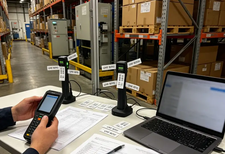
How to Test Linear and Circular RFID Antennas
A controlled field test is the most reliable way to determine which polarization suits a handheld application.
Use the same tags, operating frequency, output power conditions, and environment wherever practical.
Step 1: Establish a Reference Configuration
Choose representative RFID tags and attach them to their intended materials.
Record the tag model, mounting position, reader configuration, and test distance.
Start with an unobstructed environment to establish baseline performance.
Step 2: Test Different Tag Orientations
Rotate the tag or change the reader orientation through representative positions.
For example, test horizontal, vertical, and intermediate angles.
Observe whether the reader continues detecting the tag.
A linear antenna may show noticeable variation when the tag orientation changes.
A circular antenna may provide more consistent detection, depending on the complete design.
Step 3: Measure Practical Read Performance
Avoid using a single maximum-range reading as the main result.
Instead, record repeated detections at the distances workers actually use.
| Test Metric | Purpose |
|---|---|
| Successful read percentage | Measures reliability |
| Time to first read | Evaluates responsiveness |
| Read performance by orientation | Reveals polarization sensitivity |
| Maximum repeatable distance | Establishes practical working range |
| Unexpected EPC detections | Measures read-zone control |
| Performance near metal | Shows environmental sensitivity |
Keep the test duration and scanning procedure consistent.
Otherwise, results may reflect operator technique rather than antenna performance.
Step 4: Repeat the Test in the Real Environment
Move the test to the warehouse, manufacturing area, or equipment inspection site.
Include metal shelving, machinery, nearby tagged assets, and normal inventory loading.
Reflections may change the apparent advantage of a particular polarization configuration.
Repeatable results under actual conditions provide stronger evidence than a laboratory comparison alone.
Which Polarization Should You Choose?
The decision depends primarily on tag orientation and the required reading workflow.
Linear polarization may be suitable when tags have predictable mounting positions and operators can maintain favorable alignment.
Circular polarization is often the more practical choice when tags face different directions or employees perform broad inventory sweeps.
For specialized handheld systems, consider antenna polarization alongside gain, beamwidth, reader power, tag sensitivity, and environmental conditions.
The best configuration is not necessarily the one with the greatest nominal range. It is the one that consistently reads the intended tags without excessive operator effort or unintended detections.
Conclusion
UHF RFID antenna polarization influences how efficiently handheld readers communicate with passive tags.
Linear polarization offers strong coupling when reader and tag orientations align, while circular polarization reduces sensitivity to tag rotation.
Both approaches have limitations. Metal reflections, tag mounting, antenna gain, and the reading environment can change practical performance.
Industrial teams should compare configurations using representative assets and realistic scanning procedures. Reliable field results are more useful than choosing polarization based on one specification alone.
FAQ
What is the difference between linear and circular polarization in UHF RFID?
Linear polarization uses a fixed electric-field orientation, while circular polarization uses a rotating field. Circular polarization generally handles varying tag orientations more consistently.
Is circular polarization better for handheld RFID readers?
It is often useful when tags face different directions during mobile scanning. Linear polarization may be more effective when tags remain aligned with the reader.
Does linear polarization provide a longer RFID reading distance?
It can provide a range advantage when the reader and tag antennas align correctly. Actual range depends on antenna gain, tag sensitivity, operating power, and environmental conditions.
Can circular polarization eliminate RFID interference from metal?
No. Circular polarization reduces sensitivity to tag orientation, but it does not eliminate metal reflections, antenna detuning, or shielding. Suitable tag design and placement remain necessary.
How can I determine my RFID handheld reader’s antenna polarization?
Check the manufacturer’s antenna datasheet or technical documentation. RFID chip type, antenna gain, and maximum reading distance alone do not identify polarization.
External Reference Sources
1. RAIN Alliance — RFID Antennas
2. Siemens — Guidelines for Selecting RFID UHF Antennas